The next project was aimed at automating and controlling the Gas Oil supply needs of 2 Emergency Power Generators and one tank that feeds a pump to supply gas oil to snow groomer cat trucks.
The main tanks consist of a battery of 25 double skinned tanks with a capacity of 1,000 Liters each at a 1,500 m height. The daily service tanks of each power generator unit are located at a height of 1,850 m and 1,800 m respectively. The third supply point consists of two batteries of double skinned tanks with a 1,000 Liter capacity, one battery with 8 tanks, one with 16, which in turn supply the pump, at a 1,600 m height.
Solution adopted by INPRO
Pipe Line
Double piping is used. The total distance of the pipe is 2,000 m. Pipes were selected according to the criteria of standard DIN 4755 indicating that gas oil speed in propulsion pipes must be between 1 and 1.5 m/s and in suction pipes between 0.2 and 0.5m/s.
Main tank control
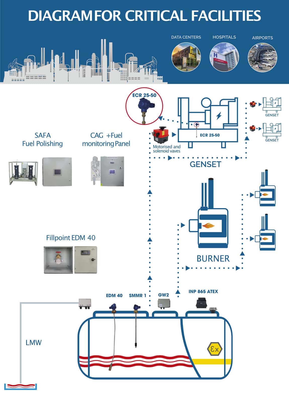
A continuous measurement analog probe is installed. It provides local reading of tank capacity via digital displays EDM-40 as well as an alarm system to prevent overfilling when unloading the tanker.
Pump Systems
The reason behind using “mixed” units, separating those units into two bodies, is that they have an operating pressure limit and if that limit is surpassed they break down; this happens with the pressure switch, the manometer and the expansion vessels. This is why these components are mounted on a bench along with the alternative control and we call it “control body”; it’s always located at the highest pumping height. The other part of the unit contains the motor pumps, filter, retention valves and vacumeter and we call it “propulsion body”; it is always located at the lowest pumping height, near the main tank.
In this case, due to the high pumping altitude, two “split” pressure units are placed in cascade, to supply both power generator units.
The propulsion body of the first unit is located at the lowest altitude (1500 m) in an area with the two main tanks. The control body of the unit is mounted on the same bench near the propulsion body of the second unit. That control unit, in the first stage, automatically pumps the gas oil to two batteries of double-skinned tanks, with a capacity of 1,000 L each (16 + 8) located at a 1,600 m altitude. At this height, a pump that suctions from the 16 tank battery is installed to provide gas oil to the snow grooming cat trucks.
In the second stage, the “propulsion body” of the second unit suctions the gas oil from the tanks located at this altitude (1,600 m) and distributes it to both power generator units. The “control body” of the second unit is located at the highest altitude, 1,850 m, where one of the power generator units is located. The second one is at a lower height, 1,800 m. For this reason, we place a filter in the supply pipe as well as a pressure reducer (1 bar), taking into account that we need a higher pressure to pump up to 1,850 m.
Daily service tank filling
Daily service tank filling is performed via the control and safety systems (filter, N.C. solenoid valve, flow container, N.O. solenoid valve, filling safety control). Solenoid valves are managed with the control panel SMMR2, which receives the corresponding tank status signals from the level probes, one for operation and one for safety, as well as an overfilling safety flow switch in the vents.
Supply pump for technical vehicles of the resort
Gas oil is supplied from one of the tank batteries at a 1,600 m altitude to the different vehicles of the ski resort. A pump with an automatic hose and a mono-phase motor pump with a flow of 100 L/min. is controlled by a DSSG-1 pressure switch that detects pressure drop upon refueling. An expansion vessel is placed for line accumulation.
IMAGES OF THE PROJECTS


Elements of the installation supplied by INPRO
PROBE EDM40
Continuous level display and control unit completely adapted to the needs of the installation. Displays the level at all times, expressed as a percentage. All required operations can be done via the relay module and the analog communication output. Customized manufacture makes this unit perfect for all kinds of tanks and a wide array of fluids.
- Standard operating temperature: 40ºC that can be adapted to reach up to 125ºC.
- Control unit in standardized module (DIN 43700) 96 x 43 x 100, can be mounted with panels.
- Flexible probe with sealed head, can be fastened with 2’’, 11/2’’ or 1’’ nuts. Mounted with aluminum or standardized flange..
- Overfilling warning alarm triggering with 95 dB acoustic signal, automatic shut-off and reset push button with IP-55 protection. It complies with the requirements of the standard MI-IP03 on “Oil Installations for own consumption”.

PRESSURE UNIT GP-GEMT
Mixed gas oil pressure unit that allows automatic supply to burners and pumping to emergency generators via pressure adjustment, at heights of over 60 meters. The start-up and stop operations with a pressure switch are conducted in the control body located at the highest part of the installation, using the pumping power of the gear pumps at high pressure that allows reaching great heights. Control cables must be laid.
Propulsion Body
- Gear electric pumps with three-phase or mono-phase supply.
- Vacumeter.
- Aluminum filter, retention valves and safety valve with exhaust line.
- Motor protection IP-55
- Alternative electronic control management system
- Vacumeter
- Aluminum filter, retention valves and safety valve with exhaust line.
Control Body
- Expansion vessel with membrane.
- Operation and minimum safety pressure switch
- Possibility of all-or-nothing outputs for incident control from central control with 3, 4 or 6 signals. GSM alarm system via SMS messages or modem connection.

COLLECTOR TRAY WITH SPILLAGE DETECTOR
Placing collector trays under certain elements of the installation is recommended. Particularly, equipment that could leak due to its characteristics or during maintenance tasks. Placing a spillage detector for the tray gives the possibility of creating protocols.
- Furnace-painted plate tray with the appropriate size for each circumstance.
- Spillage detector in the control panel and detection probe. Infrared optical sensor for oil and water, conductivity sensor for water or both, mounted on the same probe.
- Standard 1.5 m probe.
- The control unit of the detector is mounted in a box with impact-resistant plastic cover. The control unit contains two voltage free relays, one for commuting and the other one usually open.

SOLENOID VALVES
Set of solenoid valves to control the filling process and safety against spillage due to excessive levels.
- Chrome plated brass Y-shaped filter, with stainless steel 0.05 mm mesh PN16.
- Gas oil N.C. solenoid valve to control the filling process.
- A regulated and sealed container (flow limiter) adapted to the desired flow, consisting of a chrome plated brass valve and nylon seals.
- Gas oil N.O. solenoid valve to control the filling process.

LEVEL SWITCH
SMMR level switches perform the operations required for the filling process and the tank overfilling alarms and protocols. Custom manufacture based on actual needs.
- Probes manufactured from different materials to work with fluids such as gas oil, oil, water, milk, etc.
- Probe with sealed head, can be fastened with 2’’, 11/2’’ or 1’’ nuts, mounted with aluminum or standardized flange.
- For controlling pumps, solenoid valves, alarms, etc..
- Control box with relays and power supply.

PRESSURE SWITCH
Adjustable pressure switch for start-up in pressure unit according to the defined adjustment. Independent operation and safety micro switches.
- Connection by 10 mm crimp fitting for compression coupling.
- Adjustable operation pressure between 1.5 and 6.5 bar
- Adjustable safety pressure between 0.5 and 2 bar

EXPANSION VESSEL FOR OIL
Expansion vessel for oil with membrane to store fuel during the operation of the unit and absorbing possible water hammers.
- Max. Pressure 8-10 Bar
- Available capacity between 1 and 25 L.
- Temperature -10ºC and +100ºC
- Pre-load 1.5 Bar.


